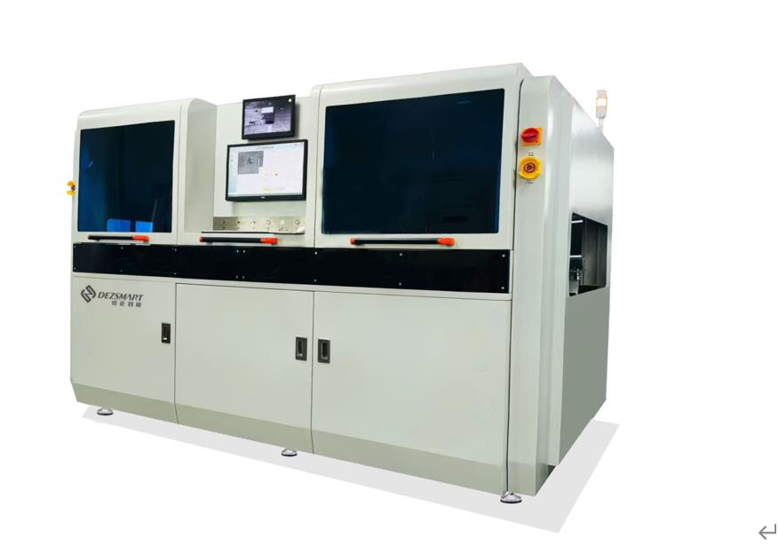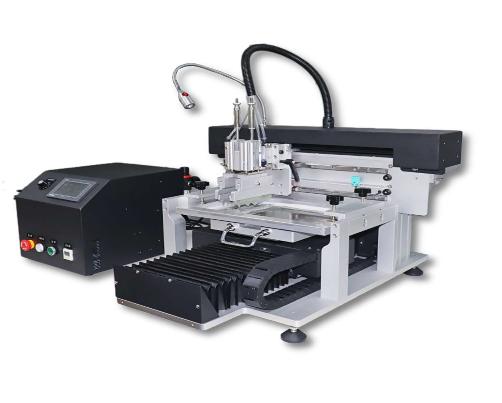
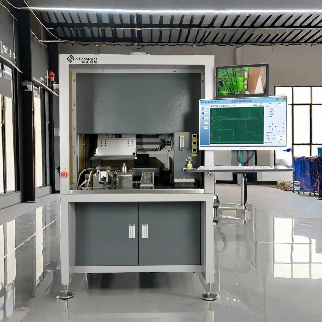
في مجال التصنيع الإلكتروني، تحدد جودة لحام ثنائي الفينيل متعدد الكلور (PCB) (لوحة الدوائر المطبوعة) بشكل مباشر استقرار المنتجات وعمرها الافتراضي ser1Tvice. وباعتبارها معدات لحام عالية الدقة، أصبحت ماكينة اللحام الموجي الانتقائي خيارًا مثاليًا للحام ثنائي الفينيل متعدد الكلور على دفعات صغيرة ومتوسطة الدُفعات بفضل مزاياها الأساسية المتمثلة في "تحديد المواقع بدقة وتقليل اللحام الخاطئ". من بينها ماكينة اللحام الموجي الانتقائي DEZ Smart DEZ-H3600A، وهي مفضلة على نطاق واسع في خطوط الإنتاج نظرًا لتصميمها المدمج والتحكم الكامل في الكمبيوتر. اليوم، سنحلل بعمق مبدأ عملها ومنطق تنسيق المكونات الأساسية والأسباب التي تجعلها قادرة على تحسين كفاءة اللحام.
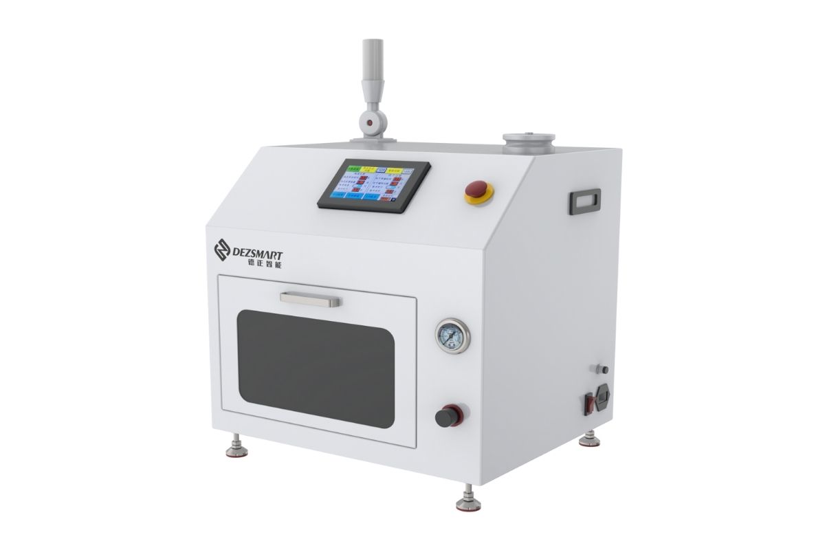
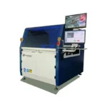
I. أولاً، تعرف على H3600A: ماكينة لحام بالموجات الانتقائية غير المتصلة بالإنترنت "مدمجة وفعالة"
II. مبدأ عمل H3600A: 4 خطوات لإكمال اللحام عالي الدقة (مع منطق تنسيق المكونات)
تتبع عملية اللحام في الماكينة H3600A منطق "المعالجة المسبقة الدقيقة + اللحام الفعال"، ويتم التحكم في العملية بأكملها بواسطة الكمبيوتر لضمان استقرار معلمات كل خطوة وإمكانية تتبعها. وعلى وجه التحديد، يمكن تقسيمها إلى 4 خطوات أساسية:
الخطوة 1: التحميل اليدوي للوحة - وضع الأساس لوضع اللحام في موضعه
أولاً، المشغل تحميل لوحة PCB يدوياً (كما هو مذكور بوضوح في المستند: "تحميل ثنائي الفينيل متعدد الكلور يدويًا") وتثبيت ثنائي الفينيل متعدد الكلور على طاولة الحركة XYZ. تعتمد طاولة العمل على تصميم خفيف الوزن، ومزودة بمحرك servo من باناسونيك وقضيب توجيه لولبي كروي. وفي وقت لاحق، يمكنها تحقيق حركة عالية الدقة بدقة ± 0.1 مم، مما يضع الأساس لدقة تحديد المواقع للرش واللحام اللاحق.
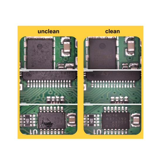
الخطوة 2: الرش بالتدفق - إزالة طبقات الأكسيد وضمان موثوقية اللحام
عندما يتم نقل لوحة PCB إلى الموضع الموجود أعلى منطقة الرش بالتدفق بواسطة طاولة العمل XYZ، تبدأ المعدات في تشغيل نظام الرش الانتقائي:
- المكونات الأساسية: تعتمد على صمام رذاذ الرذاذ المستورد (مذكور في قسم "تضمين الماكينة القياسية" من المستند) ومطابقة مع صندوق تدفق من الفولاذ المقاوم للصدأ. وهذا يضمن أن يظل ضغط الرش مستقرًا بغض النظر عن كمية التدفق المتبقية (تجنب الرش غير المتساوي الناجم عن تقلبات الضغط);
- منطق العمل: استنادًا إلى "مسار التدفق" المحدد مسبقًا (والذي يمكن برمجته مباشرةً من خلال صور ثنائي الفينيل متعدد الكلور)، يتحكم الكمبيوتر في حركة طاولة العمل XYZ، بحيث تتم محاذاة وصلات اللحام لثنائي الفينيل متعدد الكلور التي تحتاج إلى لحام بدقة مع صمام الرش، وإكمال الرش المنتظم للتدفق. وتتمثل وظيفة التدفق في إزالة طبقات الأكسيد الموجودة على وصلات لحام ثنائي الفينيل متعدد الكلور واللحام، وتقليل درجة حرارة اللحام، وتقليل خطر اللحام الخاطئ.
الخطوة 3: التسخين المسبق للقاع - تجنب الصدمة الحرارية لثنائي الفينيل متعدد الكلور وتحسين سيولة اللحام
- التحكم في درجة الحرارة: تتراوح درجة حرارة التسخين المسبق من 25 درجة مئوية إلى 240 درجة مئوية. يمكن ضبط "وقت التسخين المسبق" و"دورة التسخين (0-100%)" من خلال الكمبيوتر (يذكر قسم "التسخين المسبق" في المستند "نسبة التسخين القابلة للتعديل بواسطة الكمبيوتر الشخصي"). على سبيل المثال، يمكن ضبط وقت التسخين المسبق على 3 ثوانٍ ودورة التسخين على 50%;
- الأساسية purpose: من خلال التسخين المسبق البطيء، ترتفع درجة الحرارة الإجمالية لثنائي الفينيل متعدد الكلور بشكل متساوٍ، مما يؤدي إلى تجنب تشوه ثنائي الفينيل متعدد الكلور الناجم عن "التغيرات المفاجئة في البرودة والحرارة" عندما يتلامس مع اللحام عالي الحرارة لاحقًا؛ وفي الوقت نفسه، يتم تنشيط التدفق مسبقًا لتحسين سيولة اللحام اللاحق.
الخطوة 4: اللحام الموجي الانتقائي - توصيل وصلات اللحام بدقة لإكمال اللحام
- إعداد وعاء اللحام: يتم تسخين وعاء اللحام بواسطة سخان خارجي من الحديد الزهر. يمكن التحكم في درجة حرارة اللحام بدقة من خلال PID (تتراوح بين 25 ℃ إلى 350 ℃، مع وقت ذوبان يتراوح بين 60-90 دقيقة). وفي الوقت نفسه، فهي مجهزة بـ نظام التدفئة المضمنة N2 (نقاء N2 ≥99.99.998%) - بعد التسخين، يمكن لـ N2 عزل الهواء، وتقليل خبث اللحام الناتج عن أكسدة اللحام، وتقليل نفايات المواد;
- منطق اللحام: استنادًا إلى "مسار اللحام" المحدد مسبقًا، يتحكم الكمبيوتر في حركة طاولة العمل XYZ، مما يجعل وصلات لحام ثنائي الفينيل متعدد الكلور تلامس "قمم الموجات الانتقائية" لوعاء اللحام واحدة تلو الأخرى (يمكن ضبط ارتفاع ذروة الموجة وسرعة الحركة). المعدات مزودة بشكل قياسي بـ 5 فوهات لحام (3 قطع بقطر داخلي 4 مم و5 مم و6 مم)، والتي يمكن اختيارها وفقًا لحجم وصلات اللحام لضمان تغطية اللحام لوصلات اللحام بدقة وتجنب حدوث دوائر قصيرة ناجمة عن اللحام الزائد;
- مراقبة في الوقت الحقيقي: أثناء عملية اللحام، فإن كاميرا مراقبة في الوقت الحقيقي ينقل الصور إلى شاشة الكمبيوتر (يتم تضمين هذا التكوين في "نظام التحكم" في المستند). يمكن للمشغل مراقبة حالة اللحام في الوقت الفعلي. في الوقت نفسه، يقوم البرنامج تلقائيًا بتسجيل المعلمات مثل "درجة حرارة اللحام ودرجة حرارة N2 ومسار الحركة" وإنشاء ملفات التكوين، مما يسهل إمكانية التتبع اللاحق والاستخدام المتكرر (ضمان جودة لحام الدُفعات المتناسقة).
ثالثاً. كيف "تتعاون" المكونات الأساسية؟ تحديد مزايا اللحام في H3600A
ثالثاً. كيف "تتعاون" المكونات الأساسية؟ تحديد مزايا اللحام في H3600A


لا يمكن فصل التشغيل الفعال لجهاز H3600A عن التعاون الدقيق بين المكونات الأساسية المختلفة. وبالإضافة إلى المكونات المذكورة في العملية المذكورة أعلاه، فإن الأنظمة الثلاثة التالية بالغة الأهمية بشكل خاص:
1. نظام الحركة: "محرك مؤازر + برغي كروي" يضمن دقة تحديد الموضع
- دقة تموضع عالية: تضمن دقة التموضع المتكررة التي تبلغ ± 0.1 مم المحاذاة الدقيقة لوصلات اللحام مع الفوهات ومناطق التسخين المسبق;
- ضوضاء منخفضة: ضوضاء منخفضة أثناء التشغيل، مناسبة لبيئات الورش;
- سرعة مستقرة: يمكن ضبط سرعة الحركة من خلال البرنامج (سرعة التشغيل في الدقيقة: 25-700)، لتجنب انحرافات اللحام الناتجة عن تقلبات السرعة.
2. نظام البرمجيات: منصة ويندوز 10، "التصور + إمكانية التتبع" لتشغيل أسهل
- برمجة المسار: استيراد صور PCB مباشرة، ورسم "مسار التدفق" و"مسار اللحام" عن طريق سحب الفأرة، دون ترميز معقد;
- إدارة المعلمات: يمكن تعيين جميع المعلمات (مثل درجة حرارة اللحام ووقت التسخين المسبق وتدفق N2) وحفظها، ويمكن إنشاء ملفات التكوين لمختلف مركبات ثنائي الفينيل متعدد الكلور للاستخدام المباشر في المرة القادمة;
- مراقبة كاملة: يعرض "إحداثيات XYZ ودرجة الحرارة وعدد مهام اللحام المكتملة" في الوقت الفعلي. عندما تكون المعلمات الرئيسية غير طبيعية، سيتم تشغيل التذكيرات لتقليل معدل الخلل.
3. نظام وعاء اللحام: "مادة التيتانيوم + تسخين N2" يقلل من التكاليف ويحسن من عمر Service
- المواد: مصنوعة من سبيكة التيتانيوم، وهي مقاومة لدرجات الحرارة العالية ومقاومة للتآكل، مما يجنب تسرب اللحام الناتج عن تآكل اللحام;
- حماية N2: لا يقلل نظام التسخين المدمج N2 المدمج من خبث اللحام (تقليل نفايات اللحام) فحسب، بل يحسن أيضًا من قابلية ترطيب اللحام، مما يضمن وصلات لحام كاملة;
- سهولة الصيانة: يمكن استبدال الفوهات بسرعة. ويستخدم نظام تسخين وعاء اللحام طاقة 1.2 كيلوواط، والتي تسخن بسرعة وتستهلك طاقة منخفضة (طاقة التشغيل 1-3 كيلوواط فقط).
رابعًا. لماذا تختار H3600A؟ مزايا عملها تتطابق مباشرة مع احتياجات الإنتاج
- مدمجة وملائمة للمساحة: أبعاد الماكينة 1260 مم × 1050 مم × 1480 مم (بدون قاعدة)، ووزنها 450 كجم. وهي مناسبة لوضعها في زوايا الورشة أو بجوار خطوط الإنتاج، دون أن تشغل مساحة أساسية;
- جودة لحام مستقرة: تحكم كامل بالكمبيوتر + تحديد المواقع servo، يمكن تتبع المعلمات، والمعدل المؤهل للحام المتكرر مرتفع، مما يقلل من تكاليف إعادة العمل;
- التكامل المرن: يدعم تحميل وتفريغ اللوحة يدويًا، ويمكن أن يتعاون مع خط الإنتاج لإكمال "لحام الإصلاح" أو "لحام الدُفعات الصغيرة" دون تحويل خط الإنتاج على نطاق واسع;
- تشغيل وصيانة منخفضة التكلفة: يقلل N2 من الخبث، ووعاء لحام التيتانيوم متين، واستهلاك الطاقة منخفض. تكلفة الاستخدام على المدى الطويل أقل من تكلفة ماكينات اللحام الموجي التقليدية.
V. ما السيناريوهات التي يناسبها H3600A؟
- لحام مركبات ثنائي الفينيل متعدد الكلور صغيرة ومتوسطة الدُفعات (مثل لوحات التحكم الصناعية والوحدات الإلكترونية للسيارات);
- "لحام التصليح" أو "اللحام المخصص" بجانب خط الإنتاج (يحتاج إلى تعديل مرن لمواضع اللحام);
- متطلبات إمكانية تتبع جودة اللحام (مثل الإلكترونيات الطبية والمنتجات الداعمة للفضاء الجوي);
- مساحة الورشة محدودة، مما يتطلب معدات مدمجة غير متصلة بالإنترنت.
خاتمة